Controlling / simulating Livolo RF switches
A friend of a friend wanted to control some Livolo brand RF switches one day. The Arduino libraries didn't seem to work for him, so I got involved to see what's what.
Naturally, I can't just leave a thing be (using a library without understanding what it's doing? shivers), so what followed was an analysis of what other people have done, how the protocol works, and lasty how to simulate and use it.
The Livolo RF protocol
The protocol is a simple OOK/ASK modulated affair, at 433.92MHz.
It consists of a preamble, and 23 data bits (16 for remote ID, 7 for key press, MSB encoded) encoded in a particular way.
The whole packet takes around 8ms to send.
Lengths of "bits" look like this:

Packet preamble

Packet one

Packet zero
Short description would be:
- Preamble = ~530uS HIGH, remember nextValue will be LOW
- 1 = ~320us nextValue, remember nextValue will be negated/inverted nextValue
- 0 = ~162us nextValue, followed by another ~162us negated nextValue
So a preamble is a long-long HIGH pulse, a 1 is a long pulse, with the next one being inverted, and 0 is two short pulses (HIGH & LOW, or LOW & HIGH, depending on the number of 1s emitted).
Here is a picture of a single packet /w annotations

Annotated packet
It's important to stress that for this encoding scheme to work, the ending bit (before the nxt preamble) MUST end on a 0. This means that either a 0 must be sent (first half-period starting on HIGH, so that HIGH & LOW values occur), or a 1, sending a LOW value.
See more as to why later in the notes below.
Fun things to note
And when I say fun...
The protocol is timing sensitive. So even though it looks like the protocol could allow some deviation in the length of all these pulses, they can't be too much out of line.
The switches that decode these packets are kinda fussy... See, the receiving is (probably, to the best that I can infer) implemented on rising and falling edges. This is the reason you need a LOW at the end of each packet, so the decoder inside can latch onto the rising edge of the next preamble.
It might seem silly, but it really does seem to be implemented like that. Trying to lengthen the LOW period at the end of the packet (since, you know, it's the end) resulted in the switch ignoring the packet ><.
This also means that if you send 50 packets, the switch will only receive 49. Not a big deal, but there you go. Yes, yes, you could send another HIGH period to make it a round 50, but honestly, the switches probably won't care. Even the remote doesn't do this :p
Last packet in series
See? No high pulse, so this will most likely get ignored.
More importantly, the switches react differently to how many packets you send.
- ON/OFF commands - 25 to 30 packets is kinda the ideal. If you send more than 50, weird things start happening (lights turning ON and then back OFF or vice versa)
- DIMMING commands - a minimum of 20 packets works reliably. It sometimes works with less, but it's not recommended. This means you can dim the light on in increments, by sending >=20 packets for each UP increment.
Each button on a remote send two different key codes, depending on how you press a button.
- SHORT press - send those 25-30 packets, with a keycode X
- LONG press - continues sending packets until release, with keycode Y. Used for dimming
To synchronize/bind a key, you MUST send the ON/OFF command (SHORT press). After you put the switch into its "synchronize/learning/binding" mode of course. The switch should respond with a single beep when button is bound (at least on my test switch)-
To unbind a key, you can send the the ON/OFF sequence twice (or just a longer packet), when the switch is in its "synchronize/learning/binding" mode. The switch should responded with two beeps when it unbinds (again, works on my test unit).
This also works with a normal remote, if you double-tap a key, though I couldn't find this functionality in the included mini-manual.
Compatible RF gear
There are many ways to tackle this.
Receiving
For the receiver, you need something that gives you the RAW data (a 1 if the RF signal is present, a 0 if it is not). Some examples would be:
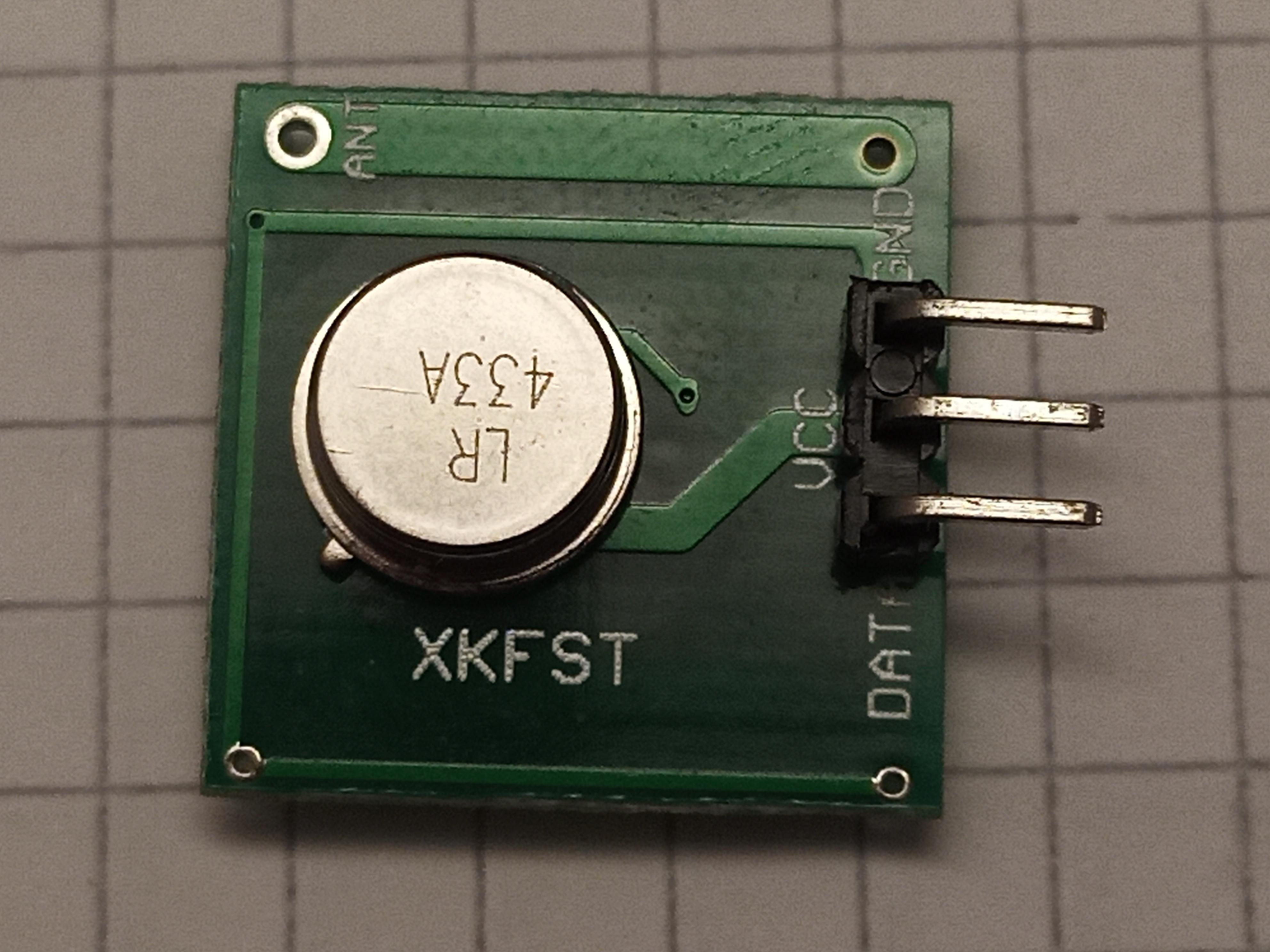
- Cheap 433MHz receivers like these
- Various RFMxx/SXxxxx modules, that have OOK output/input (like the RFM69 used here)
- Other RF chips & modules, like the CC1310
Now some modules don't exactly support receiving/transmiting this protocol, just because they require the use of packets (aka. "packet mode"). IIRC the CC1310 is one such chip, where it was necessary to implement OOK receiving by polling the RSSI register qucikly enough.
And that's the whole point, OOK is basically an if(rssi > limit){HIGH;} else{LOW;}. This also means that sometimes you can miss the beginning of a packet, while the RF receiver is updating its internal limit (it would be poor practice to just say the limit is -60dBm, as your range would suffer).
In practice, using cheap-o modules can cause you grief. This is a capture of the output of one such module:

Cheap RF receiver modules
You can see it takes a considerable time to get sort of consistent pulses out of it At 38ms/8ms, this is about 5 packets missed. This also tells us the reason, why the minimum is around 15-20 packets - the receivers need to start receiving data consistently & reliably.
The pulses aren't shaped exactly as they are transmitted either. They can vary quite a bit, so zero (HIGH & LOW or vice versa) can have a duty cycle of 66% (211us HIGH, 111us LOW, instead of 2x167us.)
Transmitting
Similar requirements to receiving exist for transmitting. At least these two should work:
Transmitting is simply a matter of turning on the transmitter, and setting the transmitter input to HIGH when you want to send a 1, and LOW when you want to send a 0.
Note, 1 and 0 represent an "RF" 1 or 0, not the Livolo RF protocol 1 or 0 or preamble.
I didn't try the cheap transmitter, but it's reported to be working. YMMV, but it should work, considering it is quite wideband IIRC.
Now the RFM69 module is quite neat. You can use the DIO2 pin to bypass the "packet mode", and output the bits as you please.
Receiving is the same - DIO2 outputs the value directly (remember the rssi>limit thing above). Just one tiny snag here, when receiving and the input signal is not present (no remotes transmitting), the pin state can vary wildly. As in it outputs junk. This means that in your code, you have to make sure to not parse data until the signal is stable. I wait until the rssi is above a threshold, and then start sampling.
Get data
FYI, I do not reccomend using interrupts for receiving, simply because noise can be an issue. On the cheap modules, fine, it isn't. But on the RFM modules it can be.
Either use something like an Input Capture unit to get the bits, or make sure your watchdog works.
Since the bits are just a serial stream, I went and implemented the receiving with the SPI module. At the SPI bitrate of 57142bps, it provides ~2x9 samples/bits per 0, ~19samples/bits per 1, and ~32bits per preamble.
Receiving is then as easy as waiting for the appropriate RSSI, reading the right number of bits (a total of 57B is needed, so go x2 and add 20%), and then combing through for the data.
This means that you'll lose some data - maybe receiving only every 2nd or 3rd or 4th packet, but it's fine for this purpose.
Send data
It's a serial stream, should also work with SPI right?
Myeah, yes and no. The switches require proper timings and those pesky rising edges. And with this here encoding scheme over SPI, there's always going to be a few bits short of a full byte at the end.
Now, testing this, it worked fine. Sending a few extra 0s at the end didn't hurt. But sending an extra byte of 0s? Stopped working.
Since I didn't want to rely on "works for me on my test setup" type of mentality, I changed the transmitting part to simply delay/block until each bit was set. This works great on PIC32, because you have a timer that counts at FCLK/2, or 12MHz in my case, which gives you very nice precision.
I mean, I was using SPI in blocking mode anyway, so...
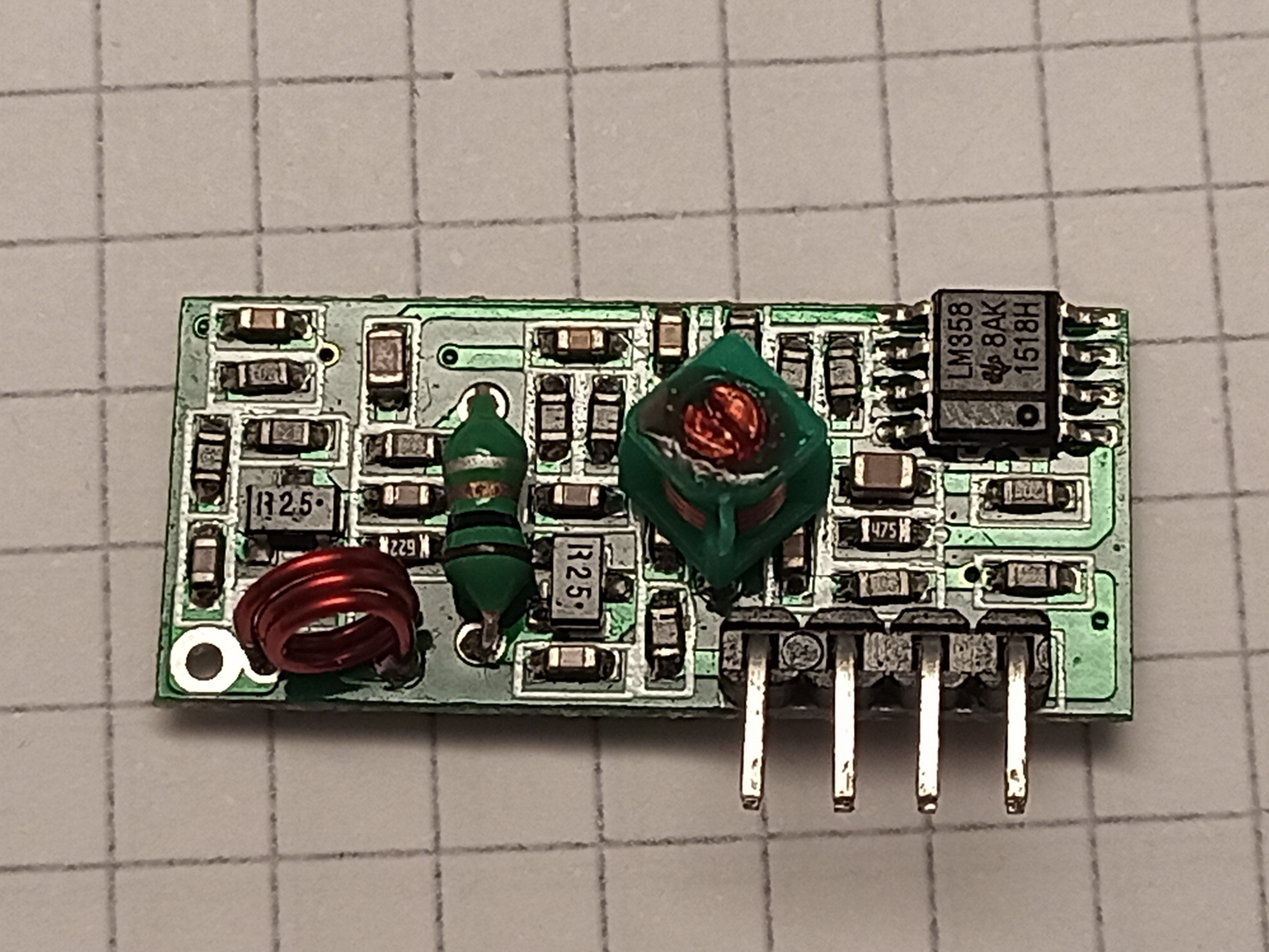
Hardware
Armed with the knowledge of how&why this thing works, I could've fixed the Arduino code and went on with my life. But we're already here, why not complicate a little bit?
A PCB was designed with the following components:
- PIC32MM0064GPL020 microcontroller
- RFM69 module
- CH340G USB-serial converter
- ABRACON ACAG1204-433-T ceramic antenna
- Multicomp MCG1901 plastic housing (Wifi dongle style)
The PCB also included provisions for a u.FL connector (either external antenna, or used for tuning), and a PI-type placeholder for a matching network for the antenna.

PCB board view
This project could've done without the CH340G converter chip, as the PIC32MM GPM family has USB support and it works with the open-source toolchain. Maybe next time.
Now, everything fits comfortably on the PCB. The problems were just that for this to be a 100% fit, the PCB should've been 1.2mm thick, and I've got the normal 1.6mm. No biggie.
The second one was, I could not for the love of me tune the antenna properly ><. Using a NanoVNA (and proper calibration), it showed the antenna resonating on its own at around 380MHz. A few hours (and days) later, the match anded up being 72nH in series with the antenna, and 1pF in parallel with the antenna. This is with the PCB in the case.
This did gave an excellent match, but with a very high-Q, so very narrow bandwidth. This means it will be susceptible to detuning quite easily...
I expected to have an easier time getting a match - datasheet states 3.0pF in series and that's it. This is probably more a shortcoming of the NanoVNA, than the antenna, but I was this close to start grinding the antenna with a power tool to shorten it.

Final tuning of antenna in case
And I managed to reverse the PGEC and PGED lines. And the RFM footprint was a bit too wide. Eh, happens.
Anyways here's [dialtone]
The HW & FW files can be found on Github. This is how the finished product looks like

Front of device

Back of device
At 0dBm transmitting power, the range is about equal to that of the remote. I have to admit, I was hoping for even better results, but this'll do for now. Bumping it up to 12dBm increases the range a bit (we're talking inside a house here, not open air), but if the antenna detunes, this could cause damage to the IC. So 0dBm it is.
A very simple command parser runs on the micro and executes what you want to do. Currently does:
- Receiving Livolo packets
- Sending Livolo packets
- Performing an RSSI sniff across a range (so you can see where the remote or other devices work)
- Dumping some debug information
Good enough.
Lessons
Just draw a PCB antenna next time. If it ends up being a narrowband match, it might as well be free.