Undervolting mobile Sandy bridge & Ivy bridge processors
There's a good few laptops available right now, for very good prices, that can serve you very well. These are the likes of HP's 2560p & 2570p, and the likes of Lenovo's x220 and x230. Very nice machines, upgradeable, good-ish battery life (they're getting old), and enough oomph to put computers of today to shame.
But the CPUs run hot. Especially if you want to get every little bit of performance out of them, and on top of that want them to be quiet.
On newer machines (Haswell and up), you can directly control the voltage of the CPU, allowing for undervolting. This is quite effective and goes a long way to help with the computer being quiet and less hot at the same time.
But Sandy/Ivy bridge don't support that. Sadly it's locked out, and only available in top of the line desktop motherboards/chipsets.
Well heck that. I want to undervolt the CPU in my machine, and I am going to do it. Or the machine will get toast and this will be a reason to upgrade. Win-win either way.
What to expect
There are a few posts online, that talk about the potential of undervolting Ivy bridge CPUs. Apparently they run really hot, and have a lot of margin, which is really good.
In the first link, the author describes a 195mV undervolt on a desktop Ivy bridge CPU, so we're hoping for something like that.
The patient
My machine of choice is an HP 2560p, upgraded with a 2570p motherboard for Ivy Bridge support (HD4000 GPU specifically is what I was after, otherwise the Sandy bridge motherboard would've stayed).
Both 2560p and 2570p are great - 16GB DDR3L support, i7 quad-core support, easily swappable battery, upgradeable wifi, place for a SATA drive and a DVD drive, 3 USB ports, etc. The screen is the weak point of this machine, but also not the main point of this machine.
The CPU I've got is an i7-3840QM ES (engineering sample). It was quite cheap on the local flea-bay, and too good to pass up. But it gets hot, and the computer becomes loud, and uggggggggggggggh.
So that's what we're dealing with, trying to undervolt an i7-3840QM for fun. It's a 45W CPU, so it overwhelms the cooling system rather quickly.
Vector of attack
The reason I'm so stuck-up on the 2560p/2570p combo is because there is a schematic available for the 2560p. Sadly there's no schematic for the 2570p, but the machines are similar enough to tell us what's going on
Our options for undervolting are:
- SW undervolt like in Haswell (no-go, not supported, too much time&effort for me atm)
- Cooler running CPU (kind of defeats this whole ordeal)
- HW mod to reduce the voltage
Since a schematic is available, the HW mod is my goto.
How the power supply works
The power supply for the CPU is a multi-phase buck converter, that takes the +12V from the battery or +19V from the charger, and converts it to the required 0.6-1.2V range needed by the CPU. In the 2560p it is based on the ISL95831 and on the 2570p it is based on the ISL95836. Both work similarly, which is great news for us. Schematics aren't public, but a simple internet search will lead you to them.
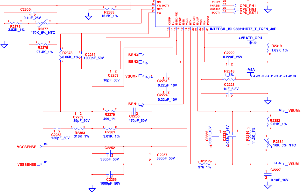
This is an excerpt of the power supply schematic. It is very similar to the reference design in the ISL95831 datasheet, just with tuned values for a particular machine.
Cropped out is the SVID interface, which is like a 1V I2C interface, through which the CPU sets the voltage. A man-in-the-middle attack could be successful, but I'm lazy and don't want to implement all the edge cases. Let's keep looking.
The voltage itself is sensed via the VSSSENSE and VCCSENSE pins coming directly off the CPU die. This allows for compensation of voltage drop due to large currents. Remember, 45W @ 1V = 45A, which will produce a non-neglible voltage drop on the PCB tracks.
The output voltage is sensed and regulated with the FB pin. With the help of this feedback pin, the DCDC chip knows what the voltage is and how to react. Now, typically in a "normal" DCDC converter, you would have a resistor divider setting a fixed output voltage. Here there is more integration, and the voltage is sensed directly. It goes through resistor R2381 (called R_DROOP in the ISL datasheet) and RC combination R2379 & C2255, but there is no divider resistor from the FB pin. Well, at least not as we would traditionally expect it to be.
So if we can't mess with the divider settings, what else can we do?
We fake it.
An idea is born
So here's the general idea. If we want to have for example a 70mV undervolt, we want to increase the sensed voltage by those 70mV. Simple right?
Try 1
The datasheet mentions, that the output voltage is dependent on VCCSENSE, VSSSENSE, the VDAC and the R_DROOP resistor + current(s).
Calculating the current over the resistor at specified voltages suggsted that it would be possible to decrease the resistor, which would decrease the output voltage. The 2.0x kohm resistor (2570p machine) was reduced by 10%, then 20% (piggy-backed resistors in parallel), and the system was tested.
It didn't seem to do much to be honest. Voltages seemed to be lower than what cpu-x was reporting, but realistically, nothing happened.
Well, at 20% the system started ocasionaly delaying my mouse&keyboard, but that was be due to enabling all options in powertops tuning settings (powertop --tune-all). In any case, idling power was not affected, and browsing some heavy sites still made the temperatures sky-rocket and the fan spin-up.
But the system was not unstable & didn't crash, so there's that.
Try 2
Well, the regulated voltage is a difference between VSSSENSE and VCCSENSE. Which means we would have to make VSSSENSE more negative (potentially dealing with ever so slightly negative voltages), or increasing VCCSENSE.
And that's what this post is about. I want to take the VCCSENSE line, add an offset to it, and send it forward to the DCDC converter chip. A HW MIM attack if you will.
And all we need to implement this is an opamp that is fast enough and can deal with the required voltages.
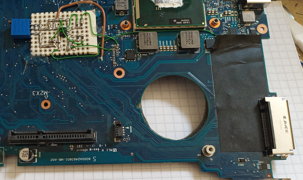
Proof of concept
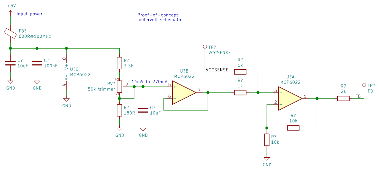
The proof of concept schematic is below.
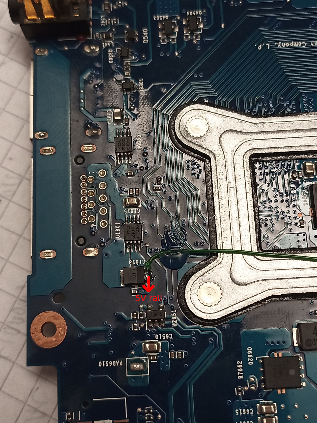
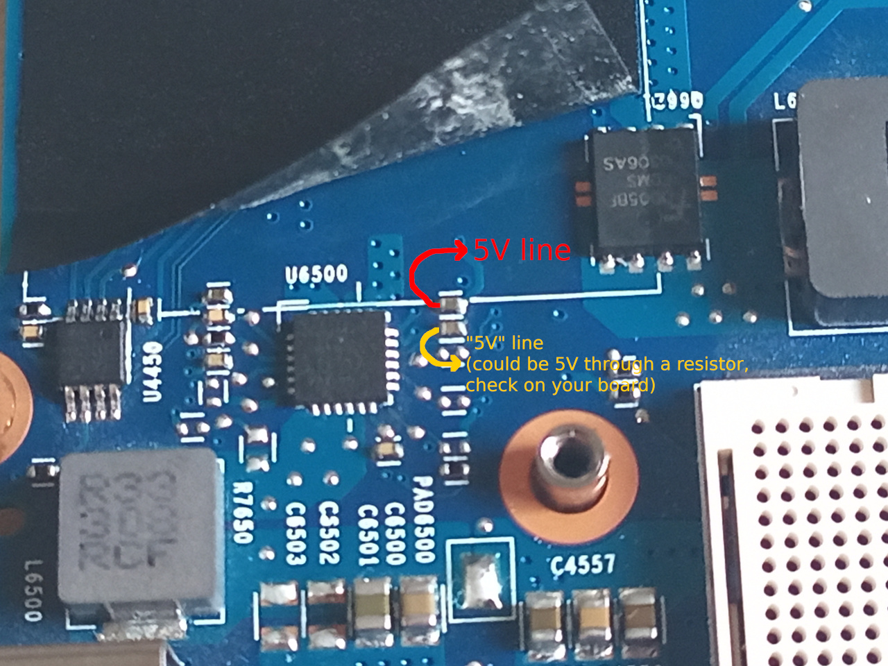
The 5V power supply rail comes off of a capacitor near the CPU. I measured that this is the same line that's used for the 5V supply for the DCDC chip, which means that we will be ON always when the DCDC chip is, which is good. This 5V supply itself is switched ON via a D82 chip, chich is a high-side power switch (so global 5V -> this 5V).
The RDROOP and RC combination is handily on the same side of the motherboard, as is the cpu/cooler/hard drive etc. Some tracing of components produced the following shcmeatic, with R_DROOP circled.
For the offset, it's generated with a resistor divider from the 5V rail, and well filtered with a 10uF capacitor. With the values choses, at 5.2V (measured on my board) you might have say 155mV, and on a 4.8V supply you'd have 143mV. Good enough.
The VCCSENSE and the offset voltage are summed together via two equal resistors - 1k in my case. The values aren't overly critical, but lower values mean less susceptibility to noise. I suggest keeping it in the 1k-10k range.
After that, the resulting voltage is amplified x2, again by using two equal resistor. The effect is that you get VOUT = VCCSENSE + Voffset.
All that's left is to remove the RDROOP resistor (3.0x kohm on 2560p, 2.0x kohm on 2570p board), put it on our board, and connect the wires to those two points. The VCCSENSE side goes to our VCCSENSE input, and our output (via resistor) goes to the FB side. Done.
But does it work
Yes ^^
The prototype was first test on a Celeron B820. A 2-core 1.7GHz Sandy bridge CPU. Since the CPU is so phenomenally underpowered, there were no obvious gains, even when using the cheapest thermal paste.
But, the CPU did undervolt pretty well, and there was a drop in temperature when under full load I think around 5°C).
The CPU ran fine on a 120mV undervolt. Pushing it past a certain mark, it would freeze under load, and would need less of an undervolt to boot. This makes sense, as the voltages are really low, and at one point there simply isn't enough to turn on the transistors inside :p
Simply stress tests were done, some rebooting to see if it boots from cold etc., and the POC was declared a success.
MORE
Of course, the point was to try this on a high-power CPU, not a potato.
So the i7-3840QM was installed, and the process was repeated.
The findings were:
- At a 185mV undervolt, the computer would freeze
- At a 175mV undervolt, it would fail prime95 rather quickly (torture test 2, 8 threads)
- At a 165mV undervolt, it would fail prime95 a bit later later (in the second pass, not the first)
- At a 155mV undervolt, the system was stable
Aw yiss.
With no undervolt, the CPU temperature would ramp up pretty quickly, and would drop the frequency by 100 or 200MHz, with the fan oscillating between fast and faster.
But with the undervolt, the CPU seemed to run happily at near 90°C on all cores, at the specified 2.9GHz or whatever it was. It should probably run faster, but since we're lying to the system about its operating conditions, this is still good enough. We might be hitting some TDP limit, or the computer wasn't set for max power (donor motherboard with locked BIOS).
What does this mean for our thermals and power consumption?
Well, runing powertop, and seems like there is little to no difference when idling.
It could be that there is some efficient power-down thing going on, or it could be that since I only replaced the RDROOP resistor and not the compensation network, that this has some adverse effect. Shouldn't though, since it's passing AC changes, and those are same, just with an added DC offset... Anyway, I originally left the compensation network connected to VCCSENSE instead of our modified output, just in case something went wrong. Since the under-load power consumption was better, I didn't bother in the POC.
Running powertop while under load (stress --cpu 8), shows a MASSIVE difference, of around 9-10W!
- No undervolt, around 37-38W
- With undervolt, around 28W
Now these number aren't highly scientific, but considering:
- The system shows lower consumption
- The thermals were improved, with less thermal throttling and lower fan speed
I'm ready to call this good enough.
(Again, don't quote me on these numbers, please. There are way too many places where I could've made a mistake, and I don't want to repeate these tests).
Where to go from here
A couple of things are left to explore.
- Integrate & test the compensation network
- Try with a slower/low-power opamp (update, do not recommend)
- Make PCB and integrate into production machine
- Fake the GPU voltage / undervolt the GPU (done, works)
- Fake the current and unlock the TDP limit
In reverse order, the current limit is intriguing, but there are multiple factors that change at the same time with simple mods. Maybe for that rainy day, when I really need all cores at 3.6GHz.
I don't think undervolting the GPU is really "the point" on this machine, so that gets a soft pass.
(UPDATE - it didn't let me sleep, so I tried it. Works fine)
A PCB will be made, and integrated in the space beneath the hard drive (original drive was 9.5mm, current ones are 7mm, so that gives us plenty of space).
A slower opamp might be good-enough, but at this point why bother? The MCP6022 used in the POC is a 10MHz chip, with a quiescent current of 1mA. At 5V this means 10mW. An MCP6002 (1MHz chip) is a tenth of this, but again, not the main point. Note that the MCP6002 would probably be ok, as the bandwitdh of the DCDC chip is around 150kHz.
(UPDATE - not recommended, can face non-boot issues)
I would try the compensation network, but I currently lack the tool to measure the capacitor on the board. And if I lose that capacitor, the system can become a bit wonky :D
Are there any dangers to doing this?
Well, there's always a possibility. Chances are that if you do something stupid and the chip starts oscillating (like losing feedback), it should turn itself off. Most good DCDC converters have some sort of protection, but don't rely on it.
Since this is done with simple resistor divider, finding the right undervolt is a bit tricky, and fairly tricky if you have multiple CPUs to test. Nothing an MCU + DAC connected to the internal I2C bus couldn't fix, but that is outside the scope of this post :D
Generally VCCSENSE and VSSSENSE should be amplified differentaly, to get the exact voltage on chip. That's not such a big problem, since we're adding voltage compared to a known GND point. The differential voltage should still be OK. Just make sure to use a GND point near the DCDC converter (I used its bottom GND pad, and a thicker wire too).
As always, since this is an unsupported mod, the manufacturer doesn't provide any warranty. I also can't guarantee you won't burn your computer, make it not work at that critical presentation, or anything else really.
Other than that, it's all good. During all of the fiddling, the system was surprisingly stable, even when changing the undervolt live (going from -14mV to -155mV and back multiple times in the same session).
Lessons
Hack your hardware. You are smarter than that lightning-infused piece of rock.
