Cheap JTAG probes and the magic smoke
JTAG/SWD/ICSP/SWIM/... programming probes can be cheap, but that doesn't mean that they are good, or that they can't be improved.
In the embedded world, there's always a lookout for the "next cheap thing". That often means questionable toolchains, proprietary tools, and challenges in SW land that you swore you'll never deal with again.
But it's cheap.
Now, let's not focus on the SW side of things. It is how it is. Thankfully many less-known arhitectures are being supported by open-source projects like SDCC, making development a breeze, even if there is no debugger available (you don't need more than an LED, right?). Heck, for personal projects, things have come so far, that if it's not possible to execute a simple apt-get install [dev-tools] for the target platform, it's not worth bothering with it.
No, this is about HW, specifically the programming/debugging adapters. The price range is from astronomical & well worth it with full-on RTOS aware tracing, to free (whatever is in your junk bin) and hopefully someone wrote a script to use it.\
On the reasonable side of the spectrum, we have things like J-Link, then vendor tools (ST-Link), and homemade tools (FTDI-based interfaces, Arduino-based programmers, etc.)
Reality check
J-Link? Worth the money. If you're a serious heavy-duty ARM developer, you probably own one. But if you're a normal developer, or just starting out, something like ST-Link is just fine.
FTDI based probes are nice because they've been around for a while, and most of the kinks have been worked out. OpenOCD has nice support, and making your own program to bang out a custom protocol is pretty trivial once you get the hang of the MPSSE engine. And the speed. Aw yea. (Note, some manufacturers use FTDI based probes + CPLDs or FPGAs, to further improve the speed, though I suspect it could be done without - TI, I'm looking at you)
But there's always room for improvement. The drive to make something better resulted in the JTAG-SWD-adapter. The design is based off of KT-LINK's design diagram, using the same FT2232H chip, for speedy communication. The pinout is similar to what you'd find on other ARM probes. Features include things like USB-C, SWD support (KT-LINKs crowning achievement), ICSP support (same path as in SWD), an on-board power supply (5V, 3.3V, 2.5V, 1.8V), logic-level UART and ESD protection.
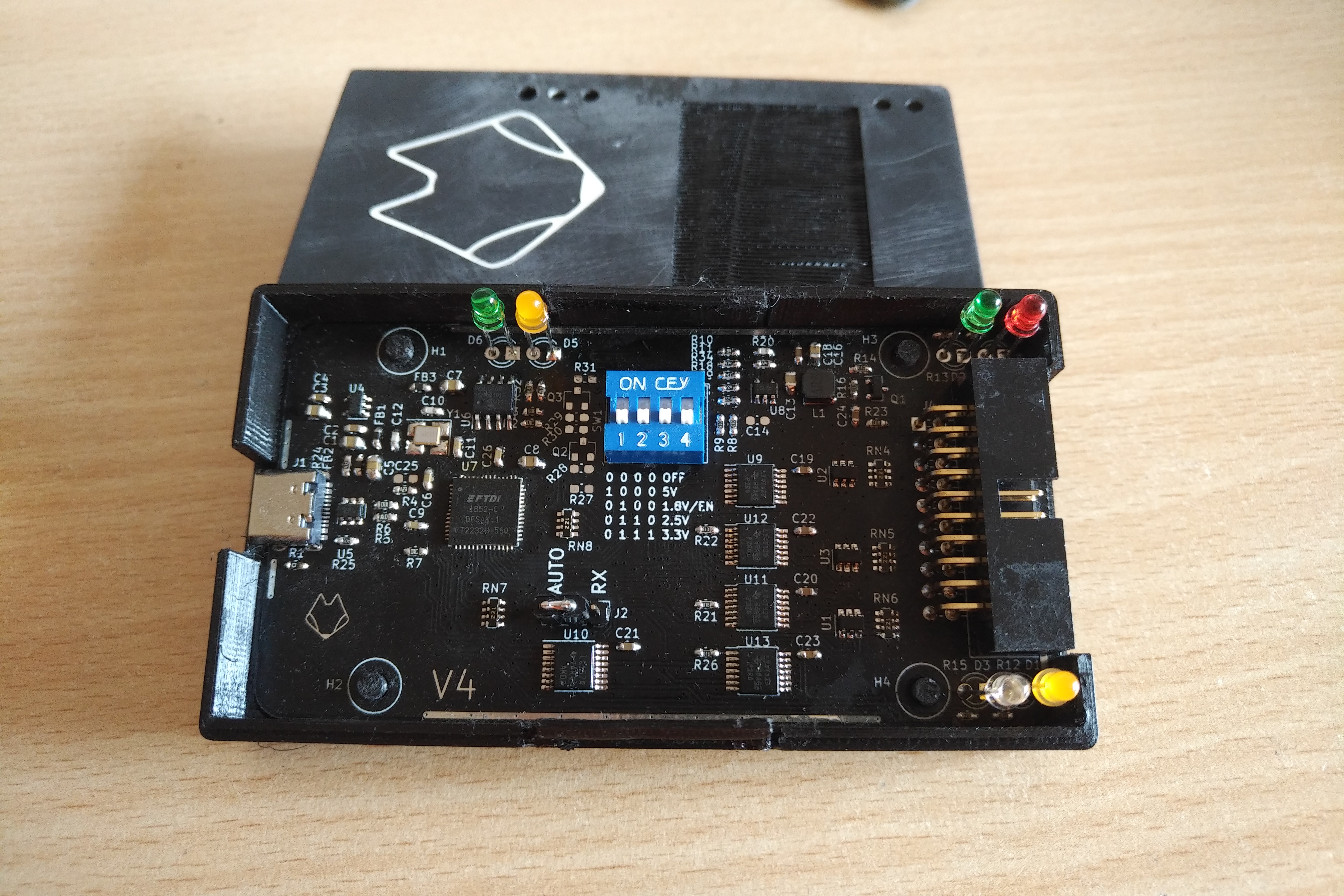
Improved adapter, for your performance
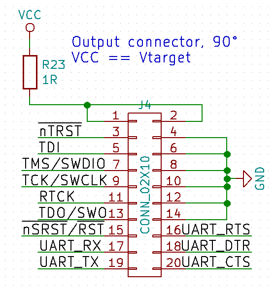
Familiar pinout, now with extra features
ESD what?
ESD - Electro Static Discharge is that zappy/sparky feeling you get every once in a while, when you walk across a carpet, or in very dry weather. Usually at most inappropriate moments... zap ... and your device stops working. Darn, you've zapped it with 10+ kV. It was your last working piece. It's Friday, and you need it working before you send it to production.
Protect your inputs
The simplest way of making your device more ESD resistant, is to add low-value resistors to your inputs & outputs. A value of 100Ω-470Ω can be used in series, to limit the current of the zap. Good probes have them (J-Link ^^), some don't (ST-Link V2's SWIM interface -.-). Adding them helps a lot, but it's not perfect.
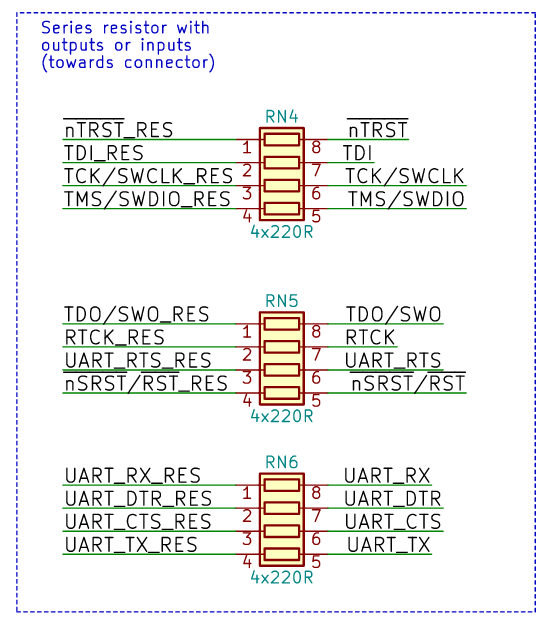
Protection resistors, for inputs and output
Another simple level of protection is having some capacitance (usually some pF) on your inputs (after the resistor, device side), or on your outputs (after the resistor, connector side). The added capacitance helps absorb the energy of the zap. This is a cheapskate way of doing it, and should not be favoured instead of proper protection. The capacitance is there usually because of EMI, so that signal edges aren't so fast to cause noise.
The proper protection is to add some ESD diodes, rated for whatever ESD level you want to achieve, and the speed of the input/output you are protecting. That usually means around 15kV Air Discharge. Something like an SRV05 is great, since it protects 4 pins and your power rail. Combine with some resistors, and you have some pretty spiffy protection.
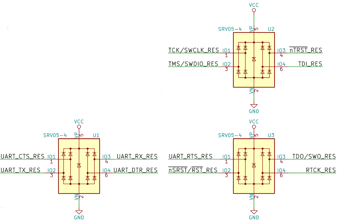
ESD diodes - the proper way
And if a zap happens? Diodes usually fail into a short. Just unsolder the diode, and continue using the device. Much faster than buying a new device :D. Of course, replace the diodes later... If you zapped them once, you will zap them again.
So if I add diodes, I'm good, right?
Yes and no. Electricity is a finicky mistress. A high energy pulse from ESD can take paths that you might not think about. Specifically, these zaps hate taking corners.
It can happen that the pulse will simply hop over to the next node in a straight path. This is where layout starts being important. Consider the two cases below:
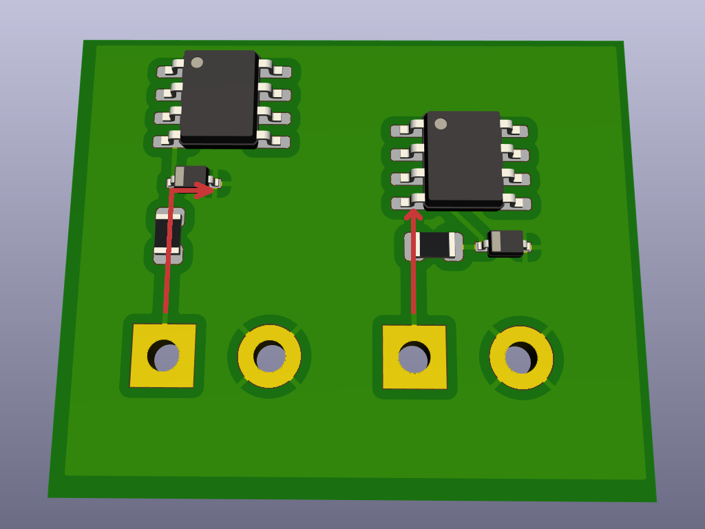
Different pulse paths
In the first case, the path is relatively straight: Connector --> Resistor --> ESD diode --> Microcontroller pin. But in the second case, since the pulse would have to snake around, it can simply jump over. Not good.
Note: The ESD diodes should normally be the first thing after the connector. If your layout permits, you can put a resistor first (like in this example), but beware of jumps. Here all connections have series resistors, so it's OK.
OK, fine, what else?
Adding some open copper (GND plane) can help with ESD (Air) discharges. Especially if your enclosure isn't air tight, or has gaps in it. A simple soldermask removal all around the edges can help quite a bit, for no additional cost.
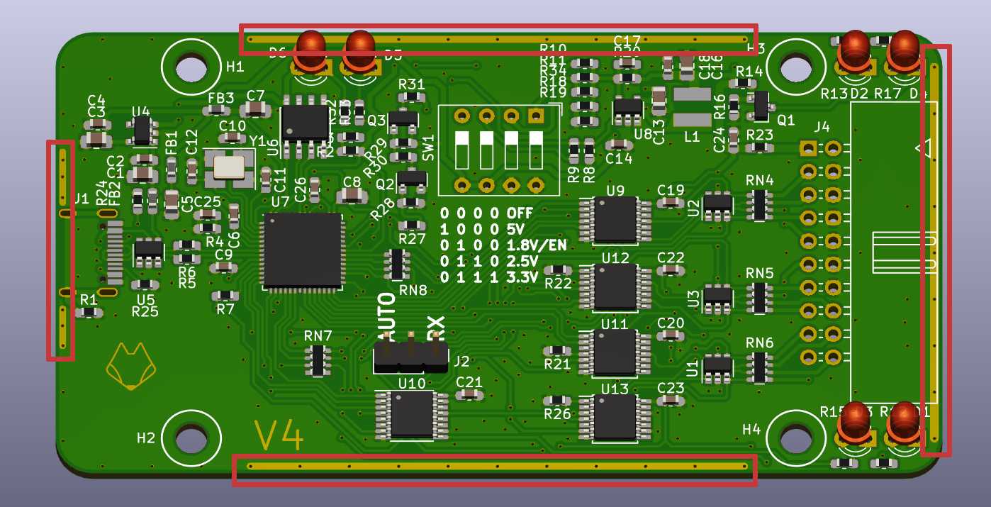
Open copper makes all the difference
This provides a low-impedance path to the spark, which is preffered over a high impedance path. Usually.
What if I want to make it bulletproof?
No.
There is a point, at which it is good enough, and it doesn't make sense to over-engineer it. If you need more than 15kV ESD protection, get better diodes, add some more capacitance, and improve your layout.
With the mods above, your device should survive ESD pulses, and even transients. For example, if you connect it to a non-earthed device, where its GND and consequently all the pins are at 1/2 line voltage (so 120V in Europe). True story... Many devices were lost due to a single non-earthed outlet. The tiny sparks should've been an obvious sign, but nobody put 2 and 2 together until it was far too late...
But that's another topic, for another day.
-- Neofoxx